Office location: Winnipeg
E-mail us: plumberswinnipeg5@gmail.com
24 Hour Service - 7 Days a Week
Page Title BG
Utilizing Leak Detection Technologies

There are several leak detection technologies commonly used in various industries. 


Here are some of the most commonly employed techniques:


  • Visual Inspection: This is a simple and straightforward method where leaks are detected by visually inspecting equipment, pipelines, or storage tanks for signs of leakage, such as visible cracks, corrosion, or liquid pooling.
  • Pressure Testing: This technique involves pressurizing a system or equipment with a gas or liquid and monitoring the pressure for any drops, which can indicate the presence of a leak. Pressure testing is commonly used during installation or maintenance of pipelines, vessels, and other pressurized systems.
  • Ultrasonic Testing: Ultrasonic leak detection utilizes high-frequency sound waves to detect leaks. Specialized instruments are used to measure the ultrasound emitted by a leaking fluid or gas, enabling the detection of leaks even if they are not visible to the naked eye.
  • Gas Detection Systems: Gas detectors are widely used to detect leaks of hazardous gases, such as methane, propane, or hydrogen sulfide. These detectors use sensors that can detect specific gases and alert operators when the concentration exceeds a predetermined threshold.
  • Infrared Thermography: Infrared cameras are used to detect leaks by capturing the temperature variations caused by escaping fluids or gases. When a leak occurs, the temperature difference between the escaping material and its surroundings can be detected and visualized using thermal imaging.
  • Tracer Gas Detection: Tracer gases, such as helium or hydrogen, are injected into a system, and specialized sensors or detectors are used to locate leaks by detecting the presence of these gases escaping from the system.
  • Acoustic Monitoring: Acoustic leak detection systems use microphones or sensors to listen for specific sounds emitted by leaking fluids or gases. These systems analyze the acoustic signals to identify and locate the source of the leak.
  • Fiber Optic Sensing: Fiber optic cables can be installed along pipelines or equipment to detect leaks based on changes in temperature, strain, or pressure. By monitoring these parameters, fiber optic sensing systems can identify the presence and location of leaks.
  • Vapor Sensing Technology: Vapor sensing systems utilize specialized sensors that can detect volatile organic compounds (VOCs) or other specific gases released by leaking substances. These sensors can be integrated into industrial processes or deployed in areas prone to leaks.

These technologies are used depending on the specific requirements of the industry, the type of material being transported or stored, and the desired level of sensitivity, accuracy, and real-time monitoring. Different combinations of these techniques can also be employed to enhance leak detection capabilities in critical applications.


Visual Inspection

Visual Inspection

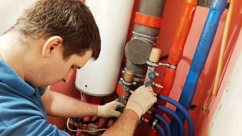
Visual inspection is a straightforward and widely used method for detecting leaks or signs of damage in various systems, equipment, or structures. It involves visually examining the components, surfaces, or areas of interest to identify any visible indications of leaks or potential leakage points. 


Here are some key aspects of visual inspection for leak detection:


  • Equipment and Systems: Visual inspection is commonly performed on pipelines, tanks, vessels, valves, connectors, seals, and other equipment or systems that handle fluids or gases. The inspector examines these components for signs of leakage, such as cracks, corrosion, loose fittings, worn-out seals, or any visible damage.
  • External Surfaces: Visual inspection may involve checking the external surfaces of equipment or structures for signs of leakage. This can include looking for discoloration, stains, wet spots, or pooling of liquid, which may indicate an active or past leak.
  • Joints and Connections: Special attention is given to joints, connectors, and connection points where leaks are more likely to occur. These areas are inspected for proper sealing, tightness, and any signs of leakage, such as dripping, seepage, or moisture buildup.
  • Corrosion and Deterioration: Visual inspection helps identify signs of corrosion or deterioration, which can weaken the integrity of materials and lead to leaks. Inspectors look for rust, pitting, flaking paint, or any other indications of material degradation that may contribute to potential leaks.
  • Physical Damage: Visual inspection also involves assessing the equipment or structure for physical damage, such as dents, punctures, scratches, or deformations that could compromise its integrity and cause leaks.
  • Leaking Fluids or Gases: During visual inspection, the presence of leaking fluids or gases may be observed directly. This could include visible drips, spray, mist, or vapor escaping from a component or system.

Visual inspection is a fundamental and initial step in leak detection, as it can quickly identify obvious signs of leakage or damage. However, it may not be sufficient for detecting smaller or hidden leaks that are not immediately visible. In such cases, complementary leak detection technologies like pressure testing, ultrasonic testing, or tracer gas detection may be employed to enhance the leak detection process.

Pressure Testing

Pressure Testing

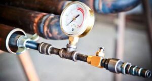
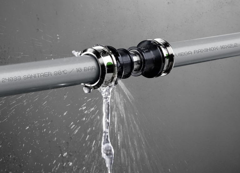
Pressure testing is a widely used method for detecting leaks and assessing the integrity of pressure vessels, pipelines, and other systems that operate under pressure. It involves subjecting the system or component to increased pressure and monitoring for any pressure drops, which can indicate the presence of leaks. 


Here are the key aspects of pressure testing:


  • Test Setup: The system or component to be tested is isolated from the rest of the process or pipeline. Valves, flanges, and other connection points are closed to create a sealed test section.
  • Pressure Application: A controlled amount of fluid, such as water or air, is introduced into the system to raise the pressure. The pressure is gradually increased to a predetermined level, typically higher than the normal operating pressure, while monitoring the pressure gauge.
  • Stabilization Period: Once the desired test pressure is reached, the system is held at that pressure for a specified period, known as the stabilization period. This allows time for the system to settle and any potential leaks to become more evident.
  • Pressure Monitoring: During the stabilization period, the pressure is continuously monitored using pressure gauges or sensors. Any pressure drop beyond an acceptable tolerance level is an indication of a leak.
  • Leak Detection: If a pressure drop is observed, the next step is to identify the location of the leak. This can be done by visually inspecting the system, listening for audible hissing sounds, using ultrasonic detectors, or employing other leak detection methods such as tracer gas detection.
  • Test Evaluation: The test results are evaluated based on the pressure drop, leak location, and the specific acceptance criteria established for the system. Depending on the industry and regulations, different allowable leakage rates and acceptance standards may be defined.
  • Repair and Retesting: If leaks are identified, necessary repairs or remedial actions are undertaken to address the issues. After repairs, the system is retested to ensure that the leaks have been successfully eliminated.

Pressure testing can be performed during the installation of new systems, as part of routine maintenance, or after repairs or modifications. It helps ensure the safety and reliability of pressurized systems by detecting leaks that could lead to equipment failure, environmental hazards, or potential accidents.


Ultrasonic Testing

Ultrasonic Testing

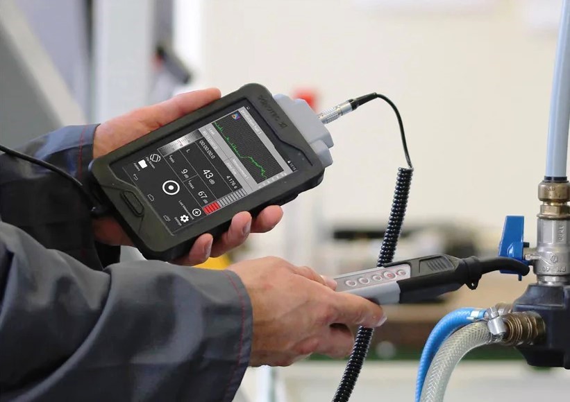
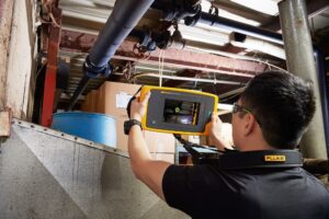
Ultrasonic testing is a non-destructive testing (NDT) method that utilizes high-frequency sound waves to detect and characterize defects, anomalies, or leaks in materials or structures. It is commonly used in various industries, including manufacturing, construction, and maintenance. 


Here are the key aspects of ultrasonic testing for leak detection:


  • Principle of Ultrasonic Testing: Ultrasonic testing involves the use of ultrasonic waves, typically in the frequency range of 1 to 20 MHz. A transducer is used to generate ultrasonic waves, which are directed into the material being tested. When the waves encounter an interface or a defect, such as a leak, they are reflected back to the transducer.
  • Transducers: Ultrasonic transducers are devices that generate and receive ultrasonic waves. They consist of a piezoelectric crystal or ceramic element that converts electrical energy into mechanical vibrations (ultrasonic waves) and vice versa. The transducer is placed in contact with or coupled to the material being tested.
  • Couplant: A couplant, usually a gel or liquid, is applied between the transducer and the material being tested. It helps ensure proper transmission of ultrasonic waves between the transducer and the material, improving the accuracy of the testing.
  • Reflection and Detection: When ultrasonic waves encounter a leak or other types of defects, they reflect back to the transducer. The transducer detects the reflected waves and converts them into electrical signals. The signals are then analyzed to identify and evaluate the presence of leaks.
  • Pulse-Echo Technique: The most common technique used in ultrasonic leak detection is the pulse-echo technique. In this method, the transducer sends a short pulse of ultrasonic waves into the material. The waves travel through the material, and any reflected waves are detected by the transducer. The time it takes for the waves to travel to and from the defect is used to calculate the distance and estimate the size or depth of the defect.
  • Visualization and Analysis: The detected ultrasonic signals are displayed on a screen as a waveform or a visual representation. Skilled technicians or analysts interpret the signals to identify and locate leaks based on the distinct patterns and characteristics of the reflected waves.
  • Advantages and Limitations: Ultrasonic testing offers several advantages, including high sensitivity, capability for both surface and subsurface defect detection, real-time results, and the ability to test a wide range of materials. However, it may require access to both sides of the material and is more effective on solid materials than fluids or gases.

Ultrasonic testing is a versatile and widely used technique for leak detection, flaw detection, thickness measurement, and other non-destructive testing applications. It provides valuable information about the condition and integrity of materials and helps prevent failures and ensure the safety of various structures and equipment.


Gas Detection Systems

Gas Detection Systems

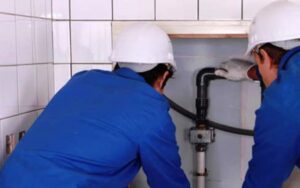
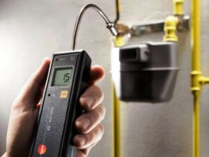
Gas detection systems are designed to monitor and detect the presence of hazardous gases in various environments, such as industrial facilities, laboratories, mines, oil and gas installations, and confined spaces. These systems play a crucial role in ensuring the safety of personnel and preventing potential accidents or health hazards. 


Here are some key aspects of gas detection systems:


  • Gas Sensors: Gas detection systems employ specialized sensors that can detect specific gases or classes of gases. Common types of gas sensors include electrochemical sensors, catalytic bead sensors, infrared sensors, photoionization detectors (PID), and metal oxide semiconductor (MOS) sensors. Each sensor type is designed to detect specific gases or target a particular range of hazardous substances.
  • Gas Sampling: Gas detection systems typically utilize a sampling mechanism to draw samples from the environment and deliver them to the gas sensors for analysis. Sampling methods can vary depending on the system design and application, including diffusion-based sampling, pump-driven sampling, or extractive sampling through sampling lines.
  • Calibration and Configuration: Gas detection systems require periodic calibration and configuration to ensure accurate and reliable gas detection. Calibration involves exposing the sensors to known gas concentrations to verify and adjust their response. Configuration allows users to set alarm thresholds, adjust sensor settings, and customize system parameters according to specific requirements.
  • Alarm and Alert Systems: Gas detection systems are equipped with alarm and alert mechanisms to notify personnel when gas concentrations exceed predefined thresholds. Visual indicators, audible alarms, and even vibration or tactile alerts are commonly employed to ensure prompt and noticeable warnings in case of gas leaks or hazardous conditions.
  • Data Logging and Analysis: Many advanced gas detection systems are equipped with data logging capabilities, allowing them to record and store gas concentration data over time. This data can be analyzed to identify trends, evaluate exposure levels, and assess the effectiveness of safety measures. Some systems may also have the ability to transmit data wirelessly for remote monitoring and analysis.
  • Maintenance and Testing: Regular maintenance, including sensor cleaning, replacement of consumables, and functional testing, is essential to ensure the proper functioning of gas detection systems. Functional tests, such as bump testing or full-scale calibration checks, are conducted to verify the system’s performance and ensure it responds correctly to gas alarms.
  • Integration with Safety Systems: Gas detection systems are often integrated with other safety systems, such as fire alarm systems, ventilation controls, or emergency shutdown systems. Integration allows for coordinated responses to hazardous situations, such as initiating evacuation procedures, activating ventilation systems, or triggering equipment shutdowns.

Gas detection systems are crucial for early warning and prompt response to gas leaks or hazardous gas concentrations. They help protect workers, prevent accidents, and mitigate the risks associated with toxic, flammable, or asphyxiant gases in various industrial and occupational settings.


Infrared Thermography

Infrared Thermography

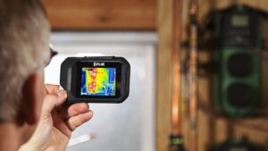
Infrared thermography, also known as thermal imaging, is a non-contact technology used to capture and visualize thermal energy emitted by objects or surfaces. It is commonly employed in various industries for leak detection, equipment inspections, energy audits, and preventive maintenance


Here are the key aspects of infrared thermography:


  • Principle of Infrared Thermography: Infrared thermography is based on the fact that all objects emit thermal energy (infrared radiation) based on their temperature. Infrared cameras detect this thermal energy and convert it into a visible image, where different colors or shades represent different temperature levels.
  • Infrared Cameras: Infrared cameras, also called thermal cameras or thermal imagers, are the primary tools used in infrared thermography. These cameras consist of an infrared detector, optics, and a display screen. They detect and measure infrared radiation across a wide range of wavelengths and convert it into a thermal image.
  • Detection of Temperature Variations: Infrared thermography is effective in detecting temperature variations on the surface of objects or equipment. It can identify areas with elevated temperatures, hotspots, or abnormal thermal patterns that may indicate potential issues, including leaks, insulation problems, electrical faults, or mechanical failures.
  • Leak Detection: Infrared thermography is commonly used for detecting leaks in plumbing systems, roofs, HVAC systems, and other applications. When there is a leak, the presence of moisture or a temperature difference between the leaking fluid and the surrounding surface can be detected through thermal imaging.
  • Insulation and Energy Audits: Infrared thermography is employed for inspecting building insulation and assessing energy efficiency. It can identify areas of heat loss or inadequate insulation, which can lead to energy wastage and increased heating or cooling costs.
  • Electrical System Inspections: Infrared thermography is widely used for electrical system inspections to detect overheating components, loose connections, faulty circuits, or other potential electrical hazards. Hotspots in electrical panels, transformers, motors, or switchgear can be identified, helping to prevent electrical failures or fires.
  • Preventive Maintenance: Infrared thermography is a valuable tool for preventive maintenance programs. It can identify early signs of equipment malfunctions, such as bearing failures, lubrication issues, or abnormal heating patterns, enabling timely interventions and minimizing downtime.
  • Data Analysis and Reporting: Infrared thermography captures thermal images that can be saved, analyzed, and compared over time. Advanced software tools are used to analyze the images, measure temperatures, and generate detailed reports. These reports provide insights into the condition of equipment or systems, identify potential issues, and recommend appropriate actions.


Infrared thermography offers the advantage of non-contact and non-destructive inspection, enabling quick and efficient detection of temperature variations and potential problems. It helps to identify hidden issues, improve safety, optimize energy usage, and enhance maintenance practices across various industries.


Tracer Gas Detection

Tracer Gas Detection

Tracer gas detection is a technique used to locate and identify leaks in various systems or equipment by introducing a detectable gas into the system and then detecting its presence or concentration at specific points. Tracer gases are gases that are safe to use, easy to detect, and non-reactive with the system being tested. 


Here are the key aspects of tracer gas detection:


  • Selection of Tracer Gas: The choice of tracer gas depends on factors such as the type of system being tested, the sensitivity required, and safety considerations. Commonly used tracer gases include helium, hydrogen, sulfur hexafluoride (SF6), nitrogen, and various halogenated gases.
  • Introduction of Tracer Gas: The tracer gas is introduced into the system or equipment under investigation. This can be done by injecting the gas into the system directly, introducing it at a specific location, or releasing it in a controlled manner.
  • Detection and Measurement: Specialized sensors or detectors are used to detect and measure the concentration of the tracer gas at various points in the system. These sensors may include mass spectrometers, gas analyzers, or specific detectors designed to sense the particular tracer gas used.
  • Leak Localization: By monitoring the concentration of the tracer gas, leaks can be located based on the higher concentration of the gas at the leak point. The concentration gradient or peak concentration is used to pinpoint the location of the leak.
  • Sensitivity and Detection Limits: The sensitivity of tracer gas detection depends on the concentration of the tracer gas used and the capabilities of the detection equipment. Tracer gas detection methods can detect leaks at very low concentrations, typically down to parts per million (ppm) or even parts per billion (ppb) levels.
  • Advantages and Limitations: Tracer gas detection offers several advantages, including the ability to detect leaks in hard-to-reach or inaccessible areas, non-destructive testing, and high sensitivity. It can be used for a wide range of systems, including pipelines, storage tanks, HVAC systems, and more. However, the technique requires introducing a tracer gas into the system and may not be suitable for detecting certain types of leaks or leaks in certain materials.
  • Safety Considerations: When using tracer gases, it is important to consider safety aspects such as the flammability, toxicity, or asphyxiation hazards associated with the tracer gas. Proper safety measures, including ventilation and adherence to safety guidelines, should be followed during tracer gas detection procedures.

Tracer gas detection is commonly employed in industries such as oil and gas, HVAC, aerospace, and industrial manufacturing. It offers an effective method for locating and identifying leaks, enabling timely repairs and maintenance to ensure system integrity and safety.

Acoustic Monitoring

Acoustic Monitoring

Acoustic monitoring, also known as acoustic leak detection or acoustic emission testing, is a technique used to detect and locate leaks or anomalies in various systems by analyzing the sound waves or vibrations generated by the leaking fluid or gas. It relies on specialized sensors or microphones to capture and analyze acoustic signals. 


Here are the key aspects of acoustic monitoring:


  • Principle of Acoustic Monitoring: Acoustic monitoring is based on the fact that leaks or structural anomalies produce distinct sound waves or vibrations that can be detected and analyzed. When a leak occurs, the escaping fluid or gas creates pressure changes and turbulence, generating acoustic emissions that propagate through the surrounding medium (e.g., liquid or gas) and can be captured by sensors.
  • Acoustic Sensors: Acoustic monitoring systems use sensitive sensors or microphones that are designed to detect and capture the acoustic signals or vibrations. These sensors can be placed directly on the surface of the equipment or structure being monitored or positioned strategically near potential leak points.
  • Signal Analysis: The acoustic signals captured by the sensors are amplified, filtered, and processed to analyze their characteristics. Signal analysis techniques, such as spectral analysis, pattern recognition, or machine learning algorithms, are applied to identify specific patterns or frequencies associated with leaks or anomalies.
  • Leak Detection: Acoustic monitoring systems can differentiate between background noise and specific leak-related acoustic signatures. By comparing the detected signals with pre-determined thresholds or reference data, leaks or anomalies can be detected, and their location can be estimated.
  • Real-time Monitoring and Alarms: Acoustic monitoring systems can provide real-time monitoring of acoustic emissions, continuously analyzing the signals and alerting operators when the acoustic patterns or intensities exceed predefined thresholds. Audible alarms, visual indicators, or remote notifications can be used to alert personnel to the presence of a leak or anomaly.
  • Applications: Acoustic monitoring can be used in various industries and systems, including pipelines, tanks, valves, pressure vessels, and other pressurized equipment. It is particularly effective for detecting leaks in fluid-carrying systems and offers advantages in scenarios where other detection methods may not be feasible or effective.
  • Advantages and Limitations: Acoustic monitoring has several advantages, such as non-intrusiveness, real-time monitoring, and the ability to detect leaks in hidden or hard-to-reach areas. It is also suitable for both liquid and gas leak detection. However, it may be less effective in noisy environments, and its sensitivity may be influenced by factors such as background noise, distance, or system complexity.

Acoustic monitoring provides an additional tool for early leak detection and can be integrated into comprehensive leak detection systems or used as a standalone method. It offers the advantage of quick detection and localization of leaks, enabling prompt response and maintenance to prevent further damage or hazards.


Fiber Optic Sensing

Fiber Optic Sensing

Fiber optic sensing is a technology that utilizes optical fibers as sensors to measure various physical parameters, including temperature, strain, pressure, and vibration. It offers several advantages over traditional sensing methods, such as long-distance sensing capabilities, immunity to electromagnetic interference, and distributed sensing along the entire length of the fiber. 


Here are the key aspects of fiber optic sensing:


  • Principle of Fiber Optic Sensing: Fiber optic sensing is based on the interaction of light with the fiber optic structure. Optical fibers are made of a core surrounded by a cladding layer, which ensures the guided transmission of light along the fiber. Certain changes in the physical parameter being measured, such as temperature or strain, can alter the characteristics of the light propagating through the fiber.

Types of Fiber Optic Sensing:

  • Distributed Fiber Optic Sensing: In distributed sensing, a single optical fiber acts as a continuous sensor along its length. Optical Time-Domain Reflectometry (OTDR) or Optical Frequency-Domain Reflectometry (OFDR) techniques are used to analyze the backscattered or reflected light signals to determine the changes in the physical parameter along the fiber.
  • Point Sensors: Point sensors use fiber optic cables with discrete sensing elements or gratings at specific points along the fiber. These sensing elements can measure parameters like temperature or strain and provide localized information at each sensing point.

Physical Parameters Measured: Fiber optic sensing can measure various physical parameters, including:

  •  
  • Temperature: Fiber optic temperature sensors utilize the temperature-dependent properties of the fiber or the absorption characteristics of certain materials applied to the fiber to measure temperature changes.
  • Strain: Fiber optic strain sensors measure the strain or deformation in structures by monitoring changes in the length of the fiber caused by mechanical stress.
  • Pressure: Pressure can be measured using fiber optic pressure sensors that use the optical properties of the fiber to detect pressure-induced changes in the fiber structure.
  • Vibration: Fiber optic vibration sensors detect vibrations or dynamic changes in structures by monitoring changes in the phase or intensity of light propagating through the fiber.

Applications: Fiber optic sensing finds applications in various industries, including:

  • Structural Health Monitoring: Fiber optic sensors can monitor the structural integrity of bridges, buildings, pipelines, and other critical infrastructure, providing real-time data on temperature, strain, and vibrations.
  • Oil and Gas Industry: Fiber optic sensing is used for downhole monitoring, pipeline monitoring, and flow assurance in oil and gas exploration and production.
  • Energy Industry: It is used for monitoring temperature and strain in power cables, wind turbines, and solar panels.
  • Transportation: Fiber optic sensors can monitor railway tracks, detect track deformations, or monitor the integrity of aircraft structures.
  • Environmental Monitoring: Fiber optic sensors can be used for landslide detection, perimeter security, or monitoring of dams and reservoirs.
  •  

Fiber optic sensing technology is continuously evolving and finding new applications across various industries. Its unique capabilities, such as distributed sensing and immunity to electromagnetic interference, make it a powerful tool for precise and reliable monitoring of physical parameters in diverse environments.


Vapor Sensing Technology

Vapor Sensing Technology

Vapor sensing technology refers to the use of specialized sensors or detectors to detect and monitor the presence of volatile organic compounds (VOCs) or other specific gases in the air. It plays a crucial role in various applications, including industrial processes, environmental monitoring, indoor air quality assessment, and safety systems.


Here are the key aspects of vapor sensing technology:


  • Sensor Technologies: Vapor sensing technologies employ different types of sensors or detectors, depending on the target gases or VOCs. 

Some common sensor technologies include:

  • Metal Oxide Semiconductor (MOS) Sensors: MOS sensors detect gases based on changes in electrical conductivity when exposed to VOCs. They are often used for general gas detection in commercial or residential settings.
  • Photoionization Detectors (PID): PID sensors use ultraviolet (UV) light to ionize VOCs, generating measurable electrical currents. They are highly sensitive to a wide range of VOCs and can detect very low concentrations.
  • Flame Ionization Detectors (FID): FID sensors are primarily used to measure organic compounds in gas chromatography. They use a hydrogen-air flame to ionize and detect the hydrocarbon molecules.
  • Electrochemical Sensors: Electrochemical sensors utilize chemical reactions at electrodes to detect and measure specific gases, such as carbon monoxide (CO) or hydrogen sulfide (H2S). They are commonly used for gas detection in industrial environments.
  • Optical Sensors: Optical sensors rely on the absorption or scattering of light by gases to detect their presence. They are used for specific gas detection, such as methane (CH4) or carbon dioxide (CO2).
  •  
  • Gas Identification and Quantification: Vapor sensing technologies can not only detect the presence of gases but also identify and quantify them. By using specific sensors or sensor arrays and comparing the measured responses to known gas profiles, it is possible to determine the type and concentration of the detected gases.
  • Real-time Monitoring and Alarms: Vapor sensing systems provide real-time monitoring of gas concentrations, continuously sampling the air and analyzing the sensor data. When gas concentrations exceed predetermined thresholds or alarm levels, visual and audible alarms are triggered to alert personnel and prompt appropriate actions.
  • Applications: Vapor sensing technology is used in various applications, including:
    • Industrial Safety: It is employed in industrial environments to detect hazardous gasses or VOCs and ensure the safety of workers. It can be integrated into safety systems, such as gas detection systems, to trigger alarms and initiate evacuation or emergency response protocols.
    • Environmental Monitoring: Vapor sensing systems are used to monitor and assess air quality, particularly in areas with potential pollution sources. They can identify and track emissions from industrial facilities, landfills, or chemical storage areas.
    • Indoor Air Quality: In residential, commercial, or institutional buildings, vapor sensing technology is utilized to monitor indoor air quality and detect harmful or odorous gasses. It helps ensure a healthy and comfortable indoor environment.
    • Process Control: Vapor sensing is used in various industrial processes to monitor and control the presence of specific gasses. It assists in maintaining process parameters, ensuring product quality, and preventing safety hazards.
  •  

Vapor sensing technology provides valuable information about the presence and concentration of gasses, enabling proactive measures to mitigate risks, protect human health, and maintain environmental standards in a range of applications.


Leave a Comment